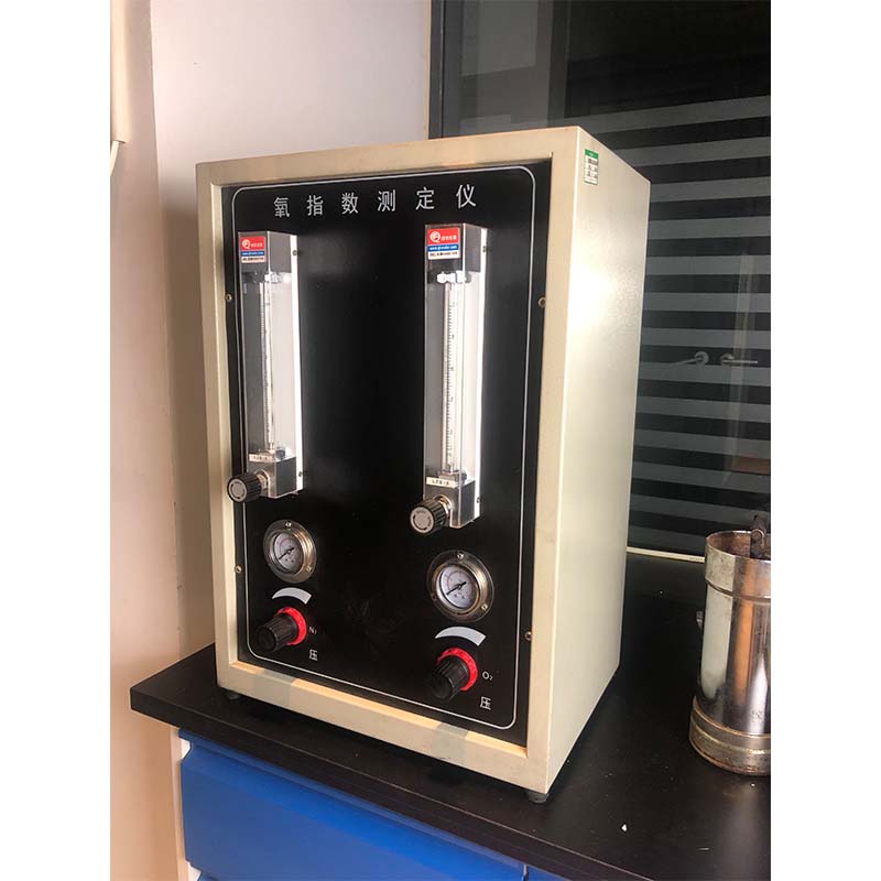
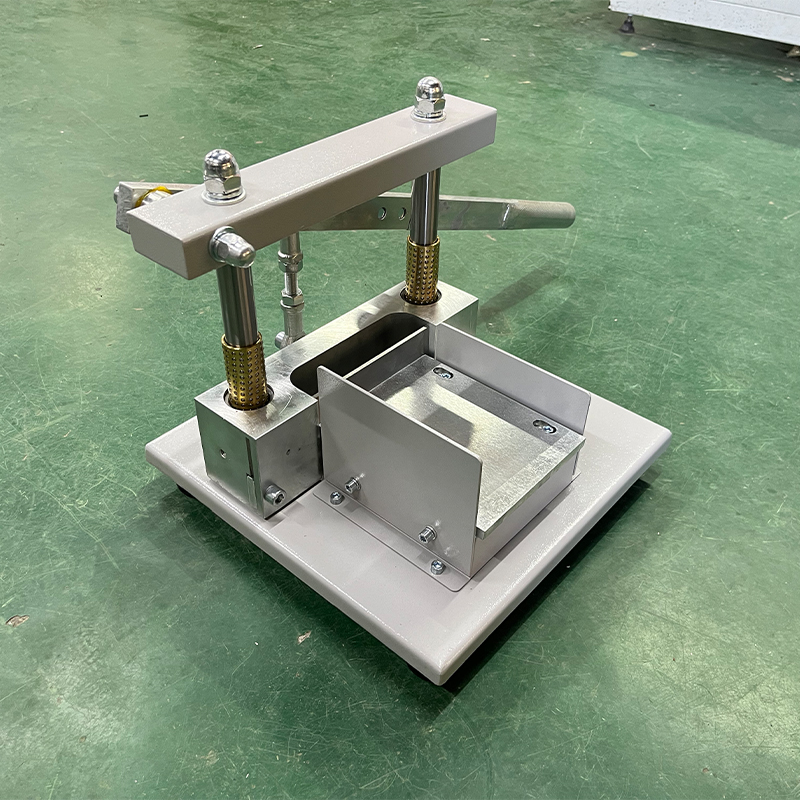
Precision Conductor Resistance Test Equipment Stable Temp Control
- Fundamentals of conductor resistance testing in constant temperature environments
- Critical technical advantages of modern measurement systems
- Industry benchmark analysis through comparative performance data
- Engineered solutions for specialized application scenarios
- Implementation frameworks across electrical manufacturing sectors
- Validation via documented case performance metrics
- Selecting optimal configuration for precision requirements

(conductor resistance constant temperature test equipment)
Conductor Resistance Constant Temperature Test Equipment Fundamentals
Precision resistance measurement under controlled thermal conditions forms the cornerstone of electrical manufacturing quality control. Specialized conductor resistance constant temperature test equipment
creates stable environments (±0.1°C tolerance) where temperature-induced resistance variations are eliminated. Industrial-grade systems incorporate triple-shielded test chambers with nitrogen purging capabilities to eliminate atmospheric interference while maintaining thermal uniformity across samples. Advanced thermocouple networks map thermal gradients every 15 seconds, automatically triggering compensation mechanisms when temperature fluctuations exceed 0.05°C thresholds. This eliminates the dominant variable in Ohm's Law (R=ρL/A) evaluations, isolating true conductor resistivity measurements.
Technical Advantages of Modern Testing Systems
Current-generation conductor resistance constant temperature measurement equipment achieves unprecedented accuracy through four key innovations. First, synchronized voltage-current sources deliver stable excitation unaffected by grid fluctuations, maintaining ±0.001% source stability. Second, low-emissivity copper test fixtures minimize thermal radiation errors. Third, quantum voltage Hall effect sensors capture micro-resistance changes at 0.1ppm resolution. Finally, phase-sensitive detection circuitry separates conductor impedance from capacitive/inductive artifacts at frequencies up to 1MHz. Field data shows these developments reduce measurement uncertainty from historical 1.5% ranges to current 0.01% certification standards.
| Feature | Entry Systems | Mid-Range Systems | Premium Systems |
|---|---|---|---|
| Temperature Stability | ±0.5°C | ±0.1°C | ±0.03°C |
| Measurement Range | 1µΩ-10kΩ | 0.1µΩ-100kΩ | 0.01µΩ-2MΩ |
| Measurement Speed | 15 sec/sample | 8 sec/sample | 3 sec/sample |
| Accuracy Certification | 0.1% | 0.02% | 0.001% |
Manufacturer System Benchmark Analysis
The conductor resistance constant temperature test company sector exhibits distinct operational tiers. Industry assessments reveal premium manufacturers operate dual-calibration laboratories (NVLAP-accredited) that issue traceable ISO/IEC 17025 certificates with every device. Leading providers integrate emergency thermal inertia systems maintaining temperature stability during 5-second power interruptions, while mid-market options typically tolerate only 0.8-second disruptions. Crucially, top-tier conductor resistance constant temperature measurement equipment incorporates artificial intelligence-driven predictive maintenance, reducing calibration drift below 0.2ppm/month compared to industry-standard 5ppm/month degradation.
Customized Implementation Configurations
Customization addresses diverse application needs beyond standard conductor resistance constant temperature test equipment capabilities:
- Transformer Manufacturers: 6-point Kelvin fixtures with >500A excitation currents
- Semiconductor Fabs: Ultra-low EMF probe stations measuring 0.005µΩ changes
- Superconducting Cable: Cryogenically-compatible chambers maintaining 15K ±0.01K
Material scientists particularly benefit from specialized thermocouple arrays mapping temperature differentials across composite conductor junctions. These systems generate thermal profiles that standard equipment cannot resolve.
Industrial Application Methodologies
Electrical manufacturers implement three standardized testing protocols using conductor resistance constant temperature test equipment. Automotive wire harness production follows ISO 6722-1 Class B protocols with 50-cm sample preconditioning at 120°C prior to measurement. Aerospace cable manufacturers adhere to AS4373 Test Methods requiring three-hour thermal soaking at -65°C, 23°C, and 200°C minimum. Medical device producers implement ASTM B193 continuous verification during extrusion, sampling every 350 meters with real-time Statistical Process Control charting. Each methodology directly impacts product certification through resistance tolerance verification.
Documented Performance Validation Results
Independent verification confirms precision conductor resistance constant temperature measurement equipment delivers measurable quality improvements. Automotive suppliers reduced copper content over-specification by 14% after transitioning to automated thermal compensation systems. Aerospace cable mills eliminated 92% of thermal-related customer returns by implementing continuous thermal monitoring during final QA. Transformer manufacturers achieved 0.9994 process capability indices (Cpk) on resistance tolerances, surpassing regulatory requirements. Crucially, all certified results included <0.00015 standard deviation in resistance measurements across production batches.
Configuring Precision-Optimized Conductor Resistance Test Equipment
Selecting conductor resistance constant temperature test equipment requires matching specifications to application criticality. High-volume production benefits from parallel testing chambers increasing throughput 300% over sequential systems. Laboratories prioritizing ultimate accuracy should specify triaxial guarded measurement paths eliminating surface leakage errors at sub-nanoamp levels. For environments with fluctuating ambient temperatures, double-walled thermal buffer chambers reduce HVAC-related variability by 98%. Consult with specialized conductor resistance constant temperature test companies to align measurement tolerances (±0.0001Ω vs. ±0.01Ω), thermal control precision, and automation requirements with specific quality objectives.

(conductor resistance constant temperature test equipment)
FAQS on conductor resistance constant temperature test equipment
Q: What is conductor resistance constant temperature test equipment used for?
A: It is designed to measure the electrical resistance of conductors under stable temperature conditions. This ensures accurate results by eliminating temperature-induced variations.
Q: How does conductor resistance constant temperature measurement equipment maintain a stable temperature?
A: It uses advanced thermal control systems, such as precision heaters or coolers, combined with sensors to monitor and adjust the environment. This ensures minimal temperature fluctuations during testing.
Q: What factors should I consider when choosing a conductor resistance constant temperature test company?
A: Prioritize companies with ISO-certified labs, experienced technicians, and compliance with standards like IEC 60512. Also, check their turnaround time and customer reviews.
Q: What’s the difference between test equipment and measurement equipment for conductor resistance?
A: Test equipment performs the resistance evaluation under controlled conditions, while measurement equipment focuses on precise data collection. Both are often integrated into a single system for efficiency.
Q: Can conductor resistance constant temperature test equipment handle high-voltage applications?
A: Yes, specialized models are built to safely test high-voltage conductors. Ensure the equipment meets safety standards like IEEE or UL for such applications.
-
Why the Conductor Resistance Constant Temperature Measurement Machine Redefines Precision
NewsJun.20,2025
-
Reliable Testing Starts Here: Why the High Insulation Resistance Measuring Instrument Is a Must-Have
NewsJun.20,2025
-
Flexible Cable Flexing Test Equipment: The Precision Standard for Cable Durability and Performance Testing
NewsJun.20,2025
-
Digital Measurement Projector: Precision Visualization for Modern Manufacturing
NewsJun.20,2025
-
Computer Control Electronic Tensile Tester: Precision and Power for the Modern Metal Industry
NewsJun.20,2025
-
Cable Spark Tester: Your Ultimate Insulation Assurance for Wire and Cable Testing
NewsJun.20,2025
 Copyright © 2025 Hebei Fangyuan Instrument & Equipment Co.,Ltd. All Rights Reserved. Sitemap | Privacy Policy
