Evaluation of Resistance Measurement Tools for Electrical Conductor Testing and Calibration
Understanding Conductor Resistance Fixture An Essential Tool in Electrical Testing
In the realm of electrical engineering, accurate measurement of conductor resistance is crucial for ensuring the reliability and safety of various electrical components and systems. One of the key tools utilized for this purpose is the conductor resistance fixture. This specialized apparatus plays a significant role in evaluating the resistance of conductive materials, ensuring that they meet established standards and specifications.
What is a Conductor Resistance Fixture?
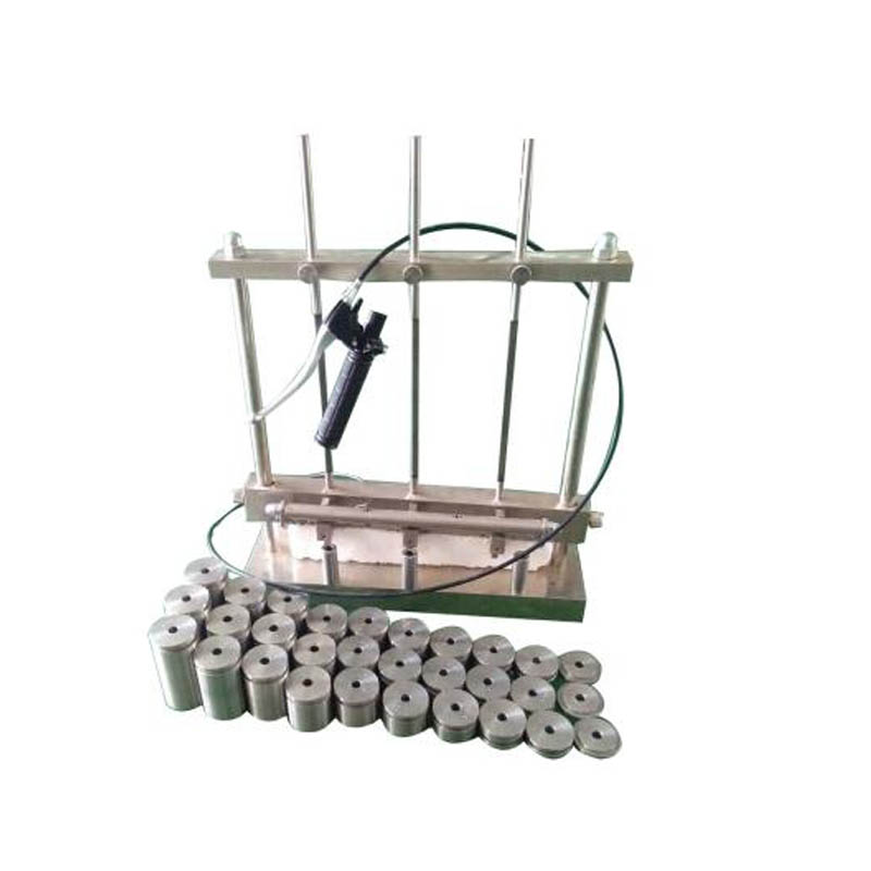
A conductor resistance fixture is a device designed to make precise measurements of the electrical resistance of conductors, such as wires, cables, and connectors. It typically consists of a set of clamps or fixtures that hold the conductor in place while connecting it to a resistance meter or ohmmeter. The primary function of this fixture is to eliminate errors that can arise from poor contact, allowing for accurate readings of the conductor's resistance.
Importance of Measuring Conductor Resistance
The resistance of a conductor is a critical parameter that influences the performance and efficiency of electrical systems. Higher resistance can lead to excessive heat generation, energy losses, and even potential failures in electrical circuits. Therefore, routine testing of conductor resistance is essential in applications such as power generation, transmission, and distribution, as well as in industrial machinery and consumer electronics.
Properly designed conductor resistance fixtures help identify substandard materials or issues in connections that can lead to outages or damage. For example, in the power industry, testing the resistance of grounding conductors can prevent dangerous faults and ensure the safety of personnel and equipment.
How the Fixture Works
conductor resistance fixture

The operation of a conductor resistance fixture involves a few key steps. First, the conductor to be tested is securely clamped within the fixture. The clamps must provide a solid and stable connection to minimize any resistance introduced by the contact points. Next, the resistance meter is connected to the fixture, which sends a small current through the conductor.
As the current flows, the meter measures the voltage drop across the conductor, allowing it to calculate the resistance using Ohm’s Law (R = V/I). This measurement can then be compared against industry standards to determine if the conductor meets the required specifications.
Applications of Conductor Resistance Fixtures
Conductor resistance fixtures find extensive application in various industries. In telecommunications, they are used to test the resistance of cables and connections to ensure optimal signal quality. In the automotive sector, these fixtures can be used to assess the resistance of wiring harnesses and connectors.
Additionally, in manufacturing processes, the fixture can verify that components meet quality standards before they are assembled into finished products. This proactive approach to quality control not only enhances product reliability but also reduces the risk of costly recalls or repairs.
Conclusion
The conductor resistance fixture is an indispensable tool in the electrical testing landscape. Its ability to provide accurate resistance measurements is vital for the integrity and safety of electrical systems. As technology advances and electrical applications become more sophisticated, the importance of precise measurements through devices like the conductor resistance fixture will only continue to grow. Ensuring high-quality conductors and connections ultimately means safer, more efficient, and more reliable electrical systems for everyone.
-
Why the Conductor Resistance Constant Temperature Measurement Machine Redefines Precision
NewsJun.20,2025
-
Reliable Testing Starts Here: Why the High Insulation Resistance Measuring Instrument Is a Must-Have
NewsJun.20,2025
-
Flexible Cable Flexing Test Equipment: The Precision Standard for Cable Durability and Performance Testing
NewsJun.20,2025
-
Digital Measurement Projector: Precision Visualization for Modern Manufacturing
NewsJun.20,2025
-
Computer Control Electronic Tensile Tester: Precision and Power for the Modern Metal Industry
NewsJun.20,2025
-
Cable Spark Tester: Your Ultimate Insulation Assurance for Wire and Cable Testing
NewsJun.20,2025
 Copyright © 2025 Hebei Fangyuan Instrument & Equipment Co.,Ltd. All Rights Reserved. Sitemap | Privacy Policy
